


The discussion in this section is based on material found in [Glasstone and Dolan 1977], The Effects of Nuclear Weapons, especially Chapter VI; and [Teller et al 1968] The Constructive Uses of Nuclear Explosives, especially Chapter 4.
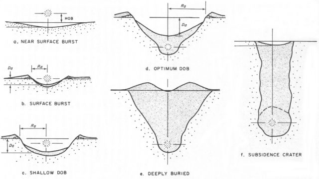
A nuclear explosion at a height well above the ground, but within the fireball radius, forms a very shallow crater largely by vaporizing the surface soil. Bursts either on the surface of the Earth (Fig. 1-a, Fig. 2-b), or slightly above it (Fig. 2-a), produce a shallow depression principally by compacting the soil beneath. Both scenarios are inefficient ways to form a crater since most the kinetic energy from the explosion dissipates in the atmosphere (upward directed energy never interacts with the ground, downward directed energy mostly reflects off and way from the ground surface). Essentially all of the radioactivity from the explosion is released into the atmosphere or deposited on the surface.
If the nuclear explosive is shallowly buried (Fig. 1-b, Fig. 2-c, Fig. 3 at >100 ft) a deeper and more voluminous crater is formed. This is due to two effects - the confinement of the soil above causes more energy to be directed downward, enhancing the compaction process, and at the same time the confining soil is blown upwards and outwards by the expanding gas, most of it falling to earth some distance from the crater.
As the depth of burial (DOB) increases the confinement effect increases, as does the amount of material lofted by the upwardly expanding gases. The average velocity of the material propelled upwards decreases as its mass increases, and the imparted motion becomes more vertical - i.e. less radial motion is imparted. As a result a larger and larger fraction of the soil thrown upward falls back into the crater (and is consequently called fallback). This tends to trap and bury much of the radioactivity.At some particular depth the increasing amount of material thrown upward is exactly balanced by the decreasing fraction escaping the crater, the crater volume reaches a maximum. This depth is called the optimum depth of burial and varies somewhat with the geology of the site, being greater for less dense and structurally weaker material (e.g. loose soil and alluvium) and shallower for dense strong rock (Fig. 1-c, Fig. 2-d, not shown in Fig. 3 but occurs between DOB 125 and 175 ft). For a 1 kt explosion in alluvium the depth is about 50 m (160 ft), in hard rock it is 43 m (140 ft). At the optimum burial depth about 90% of the radioactivity is trapped under the fallback. The largest crater produced by a U.S. explosion on land was by the Sedan test a 100 kt explosion fired at its optimum DOB (192 m).
 649x768, 41K |
 640x361, 33K 1024x578, 60K |
 681x466, 11K |
| Figure 1. | Figure 2. | Figure 3. |
 640x474, 31K |
| Figure 4. Optimum depth of burst (DOB) explosion sequence. [Teller et al 1968; p. 143] |
Figure 4 shows the various phases of expansion of an explosion at the optimum DOB. The 100 kt Sedan shot, fired at a depth 194 m in water bearing alluvium, provides a specific example of the time scale and effects. The first phase (Fig. 4-a) is the initial formation of the cavity and the expansion of the shock wave outward through the earth and upward toward the surface. Once the shock reaches the surface of the earth (Fig. 4-b)it is instantly accelerated upward, then immediately begins to deccelerate under the influence of gravity. Since the the surface of the Earth is at low (atmospheric) pressure, the high pressure driving shock wave drops to near zero, and a rarefaction (expansion)wave begins to travel back down to the cavity. As it travels deeper the rarefaction wave subjects the rock to growing tension until at some particular depth it exceeds the strength of the rock and the upper strata spall away (are split off) and fly upward unconnected to the rock below. For Sedan shot the shock wave arrived at the surface 240 milliseconds after the detonation, a point where the cavity had expanded to a radius of 55 m. The shock arrival drove the surface at 32 m/sec (about 65 mph). The expansion wave arrives back at the cavity 450 milliseconds after the detonation. The drop in pressure accompanying the rarefaction wave allows the high pressure gas in the cavity to accelerate the expansion process, and starts the gas expansion driven phase of the explosion (Fig. 4-c). The gas pressure driven expansion overtakes the decceleration of the surface at 1.3 seconds and drives it to a new high velocity of nearly 40 m/sec at 2.0 seconds. Several hundred milliseconds later the dome has stretched to its limit and begins to fracture, allowing high pressure gas and molten rock to intrude into the dome cap (Fig. 4-d). Several hundred milliseconds after that the gas escapes in an episode of massive venting (Fig. 4-e), an event which produces the sensible explosion (this occurs shortly before 4 seconds after the detonation). After several more seconds the bulk of the overburden that was thrown up has fallen back into the crater (Fig. 4-f), although the dense column of dust continues to grow to impressive dimensions over several minutes. The degree to which gas acceleration drives the explosion process is greatly affected by the water content of the rock in which the shot is fired since water vapor largely accounts for the gas pressure present during the latter part of the expansion process. The largest crater (and thus the exact optimum DOB) occurs when spallation and gas acceleration contribute equally to crater formation, or when gas acceleration dominates, depending on soil properties.
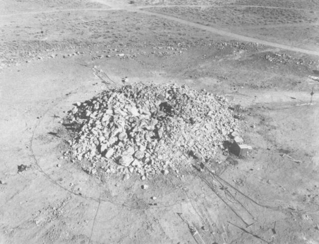
At depths greater than the optimum DOB the final crater size shrinks because so little of the material is ejected. Finally a point is reached at which effectively no material escapes from the crater (Fig. 1-d, Fig. 2-e, Fig. 3 at DOB 175 and 200 ft). There is upheaval and displacement of the soil within the crater boundary but none is thrown beyond it. At this burial depth nearly the maximum amount of broken rock is produced. Depending on the properties of the strata surrounding the detonation and overlaying it a variety of effects can occur. If the soil is mostly alluvium, which already has a disordered structured, or sand which has fluid-like behavior, the volume of the disturbed earth is essentially unchanged and it will lie more or less even with the original ground surface (Fig. 3, depth 175 ft). If the strata surrounding the detonation is bedded rock which is compressed by the formation of the lower cavity, but is overlaid by alluvium, the a shallow crater will result as the alluvium settles and fills the volume of the cavity formed (Fig. 1-d). If site is solid rock all the way to the surface (or close to it) then the formation of broken rock will increase its volume (a process called bulking) and result in a permanent rubble mound or inverse crater, known as a "retarc" (crater spelled backwards) as in Fig. 5. The bulking in the Sulky shot increased the volume of the broken rock by 50%. At this depth the material thrown into the air is driven entirely by spalling (which imparts no horizontal motion to throw material beyond the crater proper) and the gas, while not entirely confined, does not drive crater formation.
 640x489, 63K |
| Figure 5. The Sulky Shot Retarc (0.09 kt at 27.1 m in granite) |
As scaled depths become greater the shock acceleration decreases and the spalling effect weakens so that a temporary dome is created in the manner of Fig. 4-c and the cavity formed by the detonation remains intact, trapping all radiation. The temperature cools from many thousands of degrees C to 800 C in 2 to 10 seconds, and in less than a minute the pressure has dropped to the point that the lithostatic stress (the weight of the rock above) causes the cavity to collapse, and with it the mound. A high water content in the rock tends to maintain high pressures for extended periods in the cavity during cooling, thus retarding cavity collapse and prolonging the mound. It is debatable whether this temporary mound should properly be termed a "retarc".
 661x768, 30K |
| Figure 6. Full explosion containment. [Teller et al 1968; p. 128] |
At even greater depths cavity supported surface mounds do not form. Surface mounds may still form due to shock displacement at the surface, but the mounding is a permanent feature (unless a subsidence crater replaces it) and is of low relief (Fig. 6-f). The term "retarc" is not used with this type of wide, low mound not associated with surface rupture.
In a fully contained explosion the energy released by the explosion creates a spherical symmetric cavity - the discontinuity of the Earth's surface is too distant to influence the cavities formation. Continuing with a 100 kt explosion as a concrete example, for the first millisecond the growth of the cavity is driven by the "snow plow effect" - the front of the expanding shock wave. At 1 millisecond the cavity, filled with vaporized rock, has grown to a radius of 10 m and the shock pressure has dropped to one megabar (one million atmospheres). At this point the cavity growth and the shock wave become decoupled, with the shock running ahead of the expanding cavity into the surrounding rock at 5 km/sec. The cavity continues to expand over the next few hundred milliseconds until the internal vapor pressure balances the surrounding lithostatic pressure (the weight of the rock above). At a depth of 800 m this radius is about 45 m, the internal temperature at this point is several thousand degrees C. About eight times as much rock is melted as is vaporized, and the cavity is lined with about 50 cm of molten rock. Nearly all the non-volatile radioisotopes produced by the explosion are trapped in this layer of melt. Over the seconds and minutes following the explosion the molten rock drips down to from a layer on the bottom of the cavity, while continued cooling causes the pressure inside the cavity to drop below that of the lithostatic stress in the surrounding rock, allowing the ceiling of the cavity to begin to collapse.
 |
| Figure 7. Cavity formation and collapse. [Teller et al 1968; p. 129] |
Cavities formed by fully contained explosions typically undergo collapse (in U.S. tests > 95% of the time), the few cases where this does not occur is generally restricted to small cavities in salt formations. If the overburden is compact (like typical bedded rock) then the rock that falls into the cavity forms disordered rubble with greater volume than the original solid rock. Rock continues to fall from the new ceiling left by previous rock falls, causing the collapse to progress upward and form a roughly cylindrical chimney filled with rubble. When the increase in volume of the rubble over the original rock is equal to the volume of the initial cavity, the chimney has become completely filled with rubble and chimney growth ceases. If the cavity was formed at a shallow enough depth, then the chimney will grow until it reaches the surface and a permanent depression called a subsidence crater is formed (Fig. 6-a, Fig. 2-f, Fig. 3 at 350 ft). The ratio of cavity width to chimney height is quite variable, and depends on the properties of the material through which the chimney propagates. For a low porosity rock like granite is is 4.2 to 4.5; for porous rock like tuff it can range from 3.8 to 6.8. Dolomite has a low ratio of around 3.2. if the chimney encounters alluvium or sand during its upward growth, materials that do not bulk, then the ratio is essentially unlimited, the chimney will grow to the surface, even over great vertical distances.
U.S. underground tests were typically designed so that a sufficiently deep chimney of rubble was formed to form a "cap" that prevented significant amount of the volatile radioisotopes from escaping into the atmosphere.
The formation of craters through direct crater excavation are governed by scaling laws with a 1/3.4 (0.295) exponent. This is different from the cube root (1/3 or 0.333 exponent) law one would normally expect due to the effects of gravity and friction (including air resistance). Subsurface cavity formation on the other hand is not affected by these effects, and the normal cube root scaling law applies.
 640x409, 54K; 1024x654, 120K |
| Figure 8. Crater cross-section. [Glasstone and Dolan 1977; p. 254] |
| DOB = Depth of burst Ra = Apparent radius Da = Apparent depth Ral = Radius to crater lip crest Dal = Depth from the lip crest Hal = Height of the lip crest from the original ground surface Re = Radius of ejecta |
Figure 8 shows the typical features of a crater produced by a subsurface explosion in cross-section. Four regions of the crater are visible. The fallback is the ejected material that has returned to the crater, hiding the "true crater" and forming the surface of the apparent crater. The rupture zone is the region around which the detonation has has caused shattering and fracturing of the earth. Beyond this is the plastic zone where fractures are not visible but the soil has been deformed and compressed to higher than normal density. The final zone is the ejecta that forms the outer portion of the crater lip.
Cratering explosions at different depths and yields (but similar geologic conditions) can be compared by scaling them to a standard yield. The normal standard for comparison is a 1 kiloton explosion. Thus a 1 kt explosion at 50 m (163 feet) is similar in its effects (except for scale) to a 100 kt explosion at 195 m (635 feet). The formula for finding scaled depth (scaled to 1 kt) is:
A rough dimensional relationship can be expressed the crater features in Figure 8:
 640x636, 37K; 1024x1018, 79K |
 640x409, 25K; 1024x742, 53K |
| Figure 9. Scaled crater radius chart. | Figure 10. Scaled crater radius chart. |
| [Glasstone and Dolan 1977; pp. 255-256] | |
| Material | C | rho | K |
|---|---|---|---|
| Tuff | 74.75 - 77.66 | 1.8 - 2.2 | 3.8 - 6.8 |
| Granite | 57.70 - 60.48 | 2.7 | 4.2 - 4.5 |
| Dolomite | 51.31 | 2.3 | 3.2 |
| Alluvium | 64.33 - 76.45 | 2.0 | unlimited |
| Salt | 63.27 - 66.75 | 2.3 | negligible |
| Table. 1 Constants for underground detonations. [Teller et al 1968; p. 137] | |||
At a sufficently great depth an explosion forms a cavity rather than a crater. The formula for determining cavity dimensions is predicted quite well by the formula:
Once a cavity forms, it typically undergoes ceiling collapse over a period of minutes to hours to reach its final resting state. The repeated collapse of the ceiling causes a vertical chimney to form. The collapse finally halts when either the chimney is filled with loose rubble which supports the ceiling, the chimney reaches the surface and forms a subsidence crater, or (rarely, and only if the chimney radius is small) a strata is encountered that is capable of bearing the load on the ceiling. The ratio between the height of the chimney formed (measured from the shot point to the chimney apex) and the cavity radius is known by the dimensionless constant K (see Table 1), and is dependent on the characteristics of the material in which the chimney is formed -- which may be different from the material in which the cavity is formed, and may change as the chimney moves up through different strata. As can be seen in Table 1, there can be considerable variation in K even with material of similar types making predictions of final chimney dimensions inherently uncertain. There was one occasion at Nevada Test Site where a chimney unexpectedly reached the surface while an instrumentation trailer above the shot point was occupied, resulting in at least one fatality in the collapse.
 669x800, 62K; 1003x1200, 120K |
| Figure 11. Subsidence crater cross-section in alluvium. [Teller et al 1968; p. 140] |
The chimney radius is typically 10-20% greater than the original cavity radius. If a subsidence crater forms, the crater radius can provide a rough indication of the original cavity size. Allowance must be made in the increase in chimney dimension, and the possiblity of slumping at the surface if it is made of loose material. Sand for example would produce a wider and shallower crater than would be case for a solid material (hard clay, rock, etc.). Figure 11 depicts the cross-section of a typical subsidence crater in a loose material (alluvium).
In planning subsurface shots at the Nevada Test Site, attention was paid to limiting the release of volatile radioisotopes from the shot. Placing the shot deep enough so that the chimney is guaranteed to never reach the surface would be sufficient to achieve this, but deep shafts are costly to construct and a compromise approach was reached for ensuring that a sufficiently deep rubble cap would exist if a subsidence crater was formed to keep the release to a minimum. The rule of thumb was that the scaled shot deep not less than about 400 feet (122 m):
Since a 1 kt in tuff at 122 m can produce a crater with a radius of 20.2 m (Eq. 6), this suggest that a subsidence crater may form if the shot is buried in accordance with Eq. 7, since the value of K required (6.04) is within the observed range of values (Table 1), even if the test site is solid tuff all the way to the surface. If the test site is overlaid with a stratum of loose material like alluvium or sand, much lower values of K will produce subsidence craters.
So far we have not tried to specify how deep a shot must be fired to be fully contained and form a cavity, rather than breach the surface directly to form some type of crater or retarc. This is turns out to be a difficult problem to address (see [Knox 1969]). Note that surface cratering and subsurface cavity formation follow different scaling laws - a scaling law with a 1/3.4 exponent in the first case, and a scaling law with a 1/3 exponent in the second. The transition from the surface cratering regime, to that of subsurface containment involves a regime where the scaling law itself is changing and attempts at simple yield-based scaling break down. Worse still, the variable behavior of different media have a dominating effect on the precise phenomena observed. With near surface cratering and complete containment shots the balance of forces is such that the observed effects are consistent and predictable, regardless of the actual scale (absolute yield and depth) or the actual medium in the which the detonation takes place. In this transition region even shots with identical yields and burial depths can have grossly different behaviors (producing a "throwout crater" of zero depth, a retarc, or an uplift mound followed by subsidence after cavity collapse) depending on the properties of the medium. In UCID-15504, A Heuristic Examination of Scaling ([Knox 1969]), Knox employs scaling laws based on the Froude number (the ratio of inertial forces to gravitational forces) combined with ad hoc values for the material bulking ratio to achieve reasonable matches over a range of actual shots. In practice numerical simulations are used to provide reliable assessments of effects under these conditions. The NTS has adopted a simple (and very conservative) rule of thumb - that the shot should have a cube root scaled depth of at least 300 feet (92 m) to be contained.
[Glasstone and Dolan 1977] Glasstone, Samuel and Dolan, Thomas. 1977. The Effects of Nuclear Weapons, USGPO.
[Knox 1969] J. B. Knox. 1969. A Heuristic Examination of Scaling UCID-15504, Lawrence Livermore National Laboratory. https://www.osti.gov/servlets/purl/461232-VJzMBZ/webviewable/461232.pdf
[Teller et al 1968] Edward Teller, Wilson K. Talley, Gary H. Higgins, Gerald W. Johnson. 1968. The Constructive Uses of Nuclear Explosives, McGraw-Hill Book Co., LC 68-11621.